Detecting High-Impedance Ground Faults: Limitations of Standard GFDI and Active Diagnostic Solutions
Contributed By DigiKey's North American Editors
2026-03-18
In solar operations and maintenance (O&M), inverter status indicators are a primary metric for system health. However, a normal operation status does not necessarily indicate a fault-free system. Standard inverter ground fault detection interruption (GFDI) devices have detection thresholds designed to prevent nuisance tripping. Consequently, leakage currents that fall below these thresholds may go undetected.
While these currents are often insufficient to trigger a shutdown, they can cause long-term insulation degradation and equipment damage. This article examines the technical limitations of standard GFDI, the physics of high-impedance faults, and the practical challenges of locating them in 1500 V arrays. It will explore the transition from invasive troubleshooting to non-contact active diagnostics, detailing how signal injection technology identifies hidden faults to improve operational efficiency and asset longevity.
The limitations of the standard GFDI
Standard ground fault protection typically employs one of two methods: fuse-based detection (common in transformer-based central inverters) or residual current detectors (RCDs) (common in transformer-less string inverters).
Both systems function based on minimum amperage thresholds. Fuse-based systems typically require a fault current of 1 A or more to open the circuit. RCDs are generally more sensitive, with detection thresholds often around 300 mA. However, faults caused by slow insulation breakdown, moisture ingress, or wiring abrasions often begin as high-impedance connections with leakage currents well below these levels (e.g., 50 mA to 100 mA).
Electrically, this leakage remains below the trip threshold and is treated as normal operating leakage by the inverter. Physically, however, the current tracks across surfaces and generates heat, leading to carbonization and further insulation damage.
Environmental factors, such as morning dew, can temporarily lower the resistance of a fault, allowing current to flow. As moisture evaporates, resistance increases, and the fault becomes undetectable by passive monitoring. The physical damage to the conductor remains, potentially worsening with every thermal cycle.
The risks of undetected faults
A single ground fault in a floating or high-impedance grounded system locks the potential of the faulted conductor to ground. While the system may continue to operate, this condition creates a return path for current if a second fault occurs.
If a second ground fault develops on a conductor of the opposite polarity, current can bypass the inverter’s load and GFDI protection mechanisms. This creates a DC short circuit through the array’s racking or conduit.
Limitations of traditional troubleshooting methods
When a ground fault is suspected, the standard troubleshooting procedure often involves isolating strings. Technicians measure voltage at a combiner box and then physically disconnect strings sequentially to isolate the fault.
On 1,500 V systems, this process introduces specific risks. Repeatedly mating and unmating MC4 connectors can degrade seals and contacts, potentially introducing moisture or increasing resistance. Furthermore, the voltage-to-ground method requires technicians to perform manual calculations to estimate the fault's position.
Additionally, passive tools such as digital multimeters (DMMs) or insulation resistance testers (IRTs) have operational limitations in this context. A DMM identifies the presence of voltage but does not pinpoint the leak location. IRTs provide accurate insulation characterization but require the system to be de-energized and circuits to be isolated, which increases setup time.
Intermittent faults present a specific challenge for passive tools. A fault active during wet conditions may dry out by the time a technician arrives, resulting in normal voltage and resistance readings. Passive tools cannot locate a fault that is not electrically active at the time of testing. Table 1 provides a side-by-side comparison of these standard testing methods with advanced ground-fault location methods.
|
Table 1: Why traditional testing methods often fail to locate intermittent or high-impedance faults effectively. (Image source: Fluke)
Active diagnostics with the Fluke GFL-1500
The Fluke Electronics GFL-1500 solar ground fault locator is a comprehensive troubleshooting solution designed for utility-scale and commercial PV systems. As shown in Figure 1, the kit includes three essential components: the transmitter for injecting the traceable signal, the receiver for pinpointing faults along the cable path, and the signal-tracing clamp for isolating faulted strings without disconnecting conductors.
 Figure 1: The Fluke GFL-1500 solar ground fault locator includes the transmitter, receiver, and signal-tracing clamp for end-to-end ground fault location. (Image source: Fluke)
To detect high-impedance faults that standard GFDI and passive tools may miss, technicians can use active diagnostics. This method involves injecting a signal into the system to trace the fault path. The Fluke GFL-1500 solar ground fault locator utilizes this approach.
The GFL-1500 uses FaultTrack™ technology to inject a modulated frequency signal into the DC system. It operates at 6.25 kHz for fault tracing and at 32.764 kHz for open-circuit detection. These frequencies keep the signal distinct, ensuring accurate detection even in electrically noisy environments where signal clarity is typically reduced.
To maintain safety during live tracing while ensuring signal strength, the Transmitter adjusts its output current based on the selected mode. In Array HIGH mode, it outputs 30 mA RMS, while Unit HIGH mode can output up to 120 mA RMS. Furthermore, the Transmitter is dual-powered. It can operate using the array's own DC voltage or its internal batteries, ensuring consistent signal injection whether the string is energized or completely dead. This allows technicians to trace faults over long distances without generating hazardous current levels.
The device features an "Analyze" mode that characterizes the fault before physical isolation begins. By connecting the Transmitter to the combiner box, the tool measures leakage resistance and voltage to ground. It categorizes fault resistance into specific ranges (e.g., ≈ <5 kΩ, 10 kΩ, 50 kΩ, up to >1 MΩ), allowing technicians to visualize the severity of the impedance that the inverter is ignoring. Figure 2 illustrates an example of these diagnostic results on the transmitter display.
 Figure 2: The display categorizes fault resistance (e.g., <5 kΩ) and measures voltage-to-ground, allowing technicians to characterize the fault before tracing. (Image source: Fluke)
Built for rugged field conditions, the transmitter and receiver are rated IP54 for dust and splash resistance and operate over a temperature range of -20°C to +50°C. The accompanying signal clamp features a 61 mm (2.4 in) jaw opening, capable of accommodating large conductors such as 500 MCM main cables. Additionally, the receiver offers a detection range of up to 4.75 m (15.6 ft) in Array Mode, allowing technicians to trace cables in overhead racks or deep cable trays from a safe distance.
Non-invasive signal tracing workflow
The GFL-1500 allows for fault location without disconnecting high-voltage connectors. The typical workflow is as follows:
- Analyze: The technician connects the GFL-1500 Transmitter to the positive and negative busbars and the ground terminal at the combiner box or inverter, as illustrated in Figure 3. The "Analyze" function runs a diagnostic test to confirm the presence of a ground fault and measure its resistance.
 Figure 3: Wiring the GFL-1500 for analysis and signal injection. (Image source: Fluke)
- Inject: The technician initiates the signal injection. The GFL-1500 sends a tone through the system. This can be performed on energized systems (up to 1500 V).
- Trace: Using the GFL-1500 Signal Tracing Clamp, the technician scans the homerun cables. The Clamp detects the tone on the specific string carrying the fault current, allowing the technician to identify the faulted circuit among parallel strings without disconnecting wires. The handheld Receiver can also be used for tracing, though it may require isolating parallel strings for clear branch identification.
 Figure 4: Identification of the active fault path among multiple parallel circuits using the clamp without disconnecting fuses. (Image source: Fluke)
- Pinpoint: The technician follows the signal along the identified string using the Receiver. For precise detection, the device must be oriented perpendicular to the conductor as shown in Figure 5. The signal strength indicates the location of the fault, with the tone stopping or changing at the exact point of the fault. The Receiver provides both visual signal-strength bars and variable-pitch audio, allowing the technician to hear the fault location while keeping their eyes on the terrain or overhead hazards.
 Figure 5: To pinpoint the fault location, the receiver must be held perpendicular to the wiring path to maximize signal detection. (Image source: Fluke)
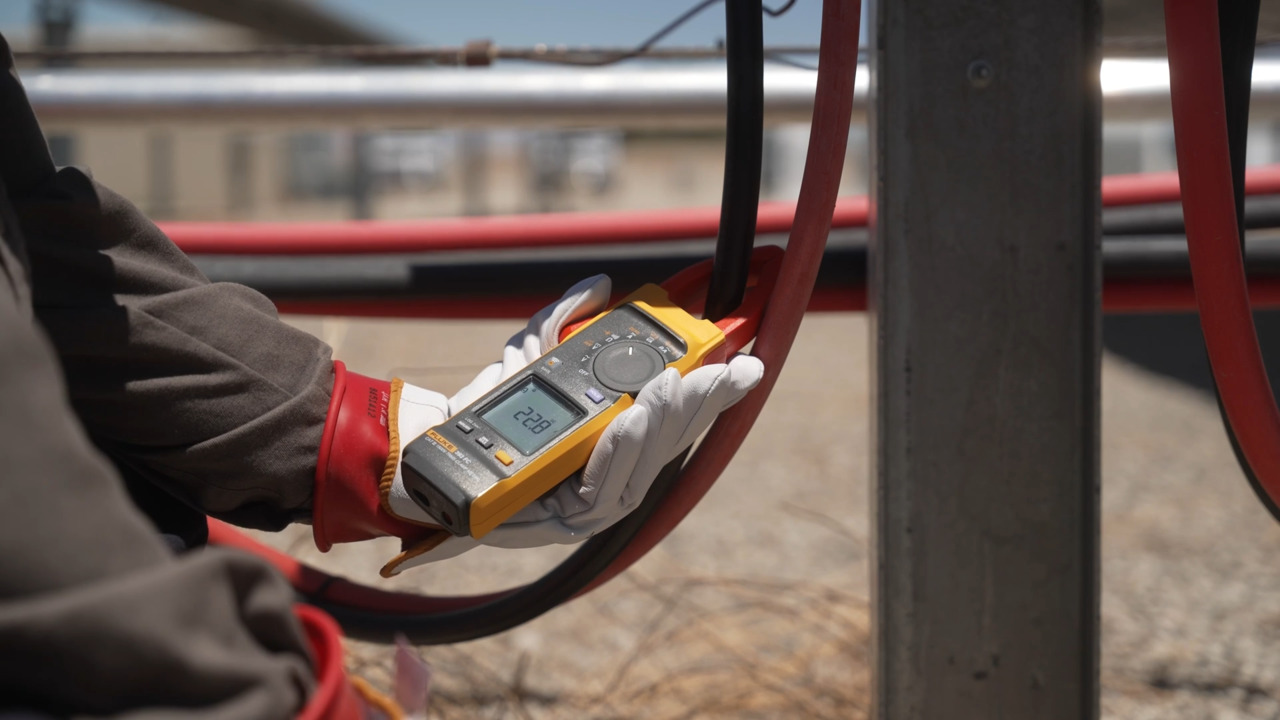
Note: Standard safety procedures, such as verifying current levels with a tool like the Fluke 393 FC clamp meter, should be followed before making any connections.
Conclusion
Inverter status indicators provide operational data but do not offer comprehensive safety assurance. As solar assets age and 1,500 V systems become standard, identifying high-impedance faults becomes increasingly important for system safety and longevity.
Adopting active diagnostic tools, such as the Fluke GFL-1500, allows O&M teams to detect faults that fall below inverter detection thresholds. This approach reduces reliance on invasive troubleshooting methods, preserves cabling integrity, and mitigates the risks associated with undetected ground faults.
Disclaimer: The opinions, beliefs, and viewpoints expressed by the various authors and/or forum participants on this website do not necessarily reflect the opinions, beliefs, and viewpoints of DigiKey or official policies of DigiKey.