Mfr Part # 4917
LED MOD RGB LINEAR STRIP
Adafruit Industries LLC
License: See Original Project Addressable LEDs Microcontrollers WS2812/SK6812 (NeoPixel) Audio LEDs / Discrete / Modules Microphone ESP32
Guide by Erin St Blaine
Get out your glue gun and get ready to make something magical.
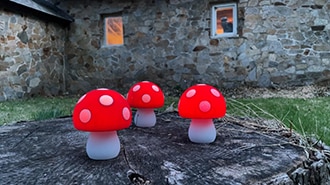
These adorable handmade mushroom lights will turn any room into a fairy forest realm, with lights that animate, change colors, and respond to sounds or music. They're made from "fairy light"-style NeoPixel LED lights, with stiff coated wires that bend easily into whatever shape you want. Coat the lights in hot glue and you get amazing light diffusion throughout the whole mushroom.
This guide will show you tips and tricks for making adorable mushroom shapes -- though you could easily use the same technique to make any number of glowing organic shapes, or even use a casting mold to make almost any shape you can imagine. The lights are connected to an Adafruit Mini Sparkle Motion board with WLED installed: a free, open-source LED programming interface that allows you or your young helpers to create endless animations and color combinations with just a few clicks -- no coding required.
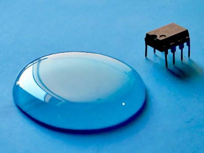
These LEDs are made from fairly stiff wire that will hold its shape when you bend and twist it. The wires are coated in durable resin, so even though they appear to be bare wire, the wires won't short against each other.
These lights are not as good for wearables or applications where they'll get flexed again and again, but they hold up very well to being twisted into shape once and secured.
They come in a strand of 100, and they are not cuttable -- or rather, you can cut the strand but can't use the cut-off part for another project.
The Mini Sparkle Motion board is an ESP32 controller designed to work with WLED. It's small and compact and will drive hundreds of lights, powered through its onboard USB-C port.
For a no-soldering version of this project, use this board with a pre-soldered terminal block.
Or, if you're comfortable with a soldering iron, this board comes in a slightly smaller, low-profile version with solderable GPIO pins.
Sculpting with hot glue can be a bit messy. This silicone mat is the perfect surface to protect your table. The hot glue will stick to it just enough to hold your mushrooms in place but then peels off clean and easy when it's set up.
You'll also need a USB-C type cable for loading the WLED software and powering the finished project and a JST connector (optional but helpful) to connect to the light strand.
1 x USB-C Cable
1 x JST Connector
One or more high-temp hot glue guns
A heat gun
A bulk pack of Hot Glue sticks (You're gonna need LOTS of glue)
A log, mirror, or other base for your mushrooms
Preserved moss for hiding the wires
A soldering iron OR a tiny flathead screwdriver for connecting the lights
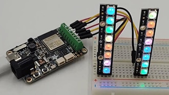
The wiring is very simple for this project. Solder or screw in your LED strip as shown:
5v --> +5v (Red wire)
32 --> DI (Middle wire)
G --> GND (Black wire)
You can either cut the included JST connector off the lights and solder / screw them directly to the board, or you can attach a mated JST connector to your board and plug the light strand in.
This page will guide you through how to install WLED on the Mini Sparkle Motion.
The Mini Sparkle Motion has a USB to serial chip which may need a driver installed before you can install WLED. Head over to the How to Install Drivers for WCH USB to Serial Chips tutorial and download and install the new driver.
These next steps require a Web Serial-compatible browser. As of this writing, that means Google Chrome, Microsoft Edge or Opera “desktop” browsers. Other browsers (Safari, Firefox, Explorer and anything mobile) won’t work.
Visit https://install.wled.me/
Plug your microcontroller into your computer with a known good USB cable. Click "Install" and select the port for your board.
Depending on the USB-to-serial bridge chip on the board, you might see one or two serial ports. On Mac, for instance, there might be both “/dev/cu.usbmodem[number]” and “/dev/cu.wchusbserial[number]”. Use the “wchusbserial” one.
After successful installation, enter your WiFi network name and password when prompted. This must be a 2.4 GHz WiFi network; ESP32 does not support 5 GHz networks. If it can’t connect, then as a fallback WLED will create its own 2.4 GHz WiFi access point.
If you don't see the "Connect to Wi-Fi" prompt, you'll need to set up your WiFi network using AP (access point) mode. Open up your WiFi settings and look for a WiFi network called WLED-AP. Connect to this network using the default password wled1234. The WLED interface will pop up in its own browser.
From here, go into Config/Wifi Settings and enter your WiFi credentials near the top. Give your project a name in the mDNS field a little further down the page. Now you can type in "projectname.local" (where "projectname" is your mDNS name) into any web browser on the same wifi network to access your microcontroller.
You can also scan the QR code below to open access point mode.
For more help and troubleshooting tips visit the Getting Started page on the WLED knowledge base.
Head to the WiFi Setup screen under Config and create a good URL so you can control your project from any web-enabled device. Call it something you'll remember, that's easy to type into any web browser on your WiFi network in order to connect to your project.
In Safari or Chrome on your phone or computer, type in this web address to access the WLED interface: http://projectname.local (where "projectname" is whatever you put into this field).
Check out the Additional Settings page for more info on accessing your project. WLED has an "access point mode" that doesn't require a WiFi network for when you're out on the go. It's also helpful to download one of the WLED apps to help manage and organize your projects.
Do this first before setting up your LED preferences with your GPIO number.
Click on "config" and head to the USERMODS tab. Scroll down a bit and you'll find the AudioReactive section.
Click the box to enable, then enter the settings and the Digitalmic section as follows:
Type: SPH0654
Pin I2S SD: 9
Pin I2S WS: 10
Pin I2S SCK: 23
The other pins are unused.
Reboot your Sparkle Motion Mini for changes to take effect.
Next, head to the LED Preferences tab under the Config menu.
Scroll down to Hardware Setup. Put your total number of LEDs into the Length field (if you're not sure yet, just put in 15), and change GPIO to pin 32, the GPIO NUMBER associated with the LED data pin on your Mini Sparkle Motion. Make sure to select the correct Color Order for your LEDs as well.
If this number appears in red and won't let you select it, check the previous step: this board is configured with pin 32 assigned to the microphone, so you need to change it there before you can set it up as your LED GPIO.
Now you can use any computer or handheld device to control your LEDs.
Make sure your device is on the same WiFi network as your board. Navigate to your custom URL (projectname.local/ ) in a web browser. You'll see a color picker above a whole bunch of color palette choices.
Choose a color, choose an effect, and watch your lights animate and glow!
Save your favorite combinations as presets, create playlists, control the speed and intensity of the animations, and lots more. This web app is incredibly intuitive and easy to use.
Head over to the WLED wiki at https://kno.wled.ge/ to delve into all the particulars.
If your lights didn't come on, here are a few things to try:
Head back to WLED and check your pinout configuration under LED Preferences. Be sure the pin number is the correct GPIO for the attachment point you used.
Check your wiring! Be sure you connected to the IN end of the LED strip. These strips can be inconsistent, so this is a pretty common problem. Use an alligator clip to try connecting the data wire on the other end (the power and ground wires should work from either end).
Try re-uploading the WLED software.
If the lights come on but you can't control them: i.e. you type in "projectname.local" into your browser and it won't connect, make sure you're on the correct WiFi network. If you're on a different network than the one you set up the software on, you won't see the WLED connection.
If your lights came on in blue or green instead of yellow, your color order is wrong. See below to fix.
If only half your lights came on, be sure you've got the correct number in the "length" field under LED preferences.
If your lights came on in a variety of weird colors and looking like a 1950s diner interior, you may have the wrong LED strip type selected. RGBW strips and RGB strips are not the same, so be sure you've got the correct strip type, or you'll get very odd behavior.
If your microcontroller hangs or keeps rebooting, or gets really hot, you may have the power and ground lines switched. Unplug right away and check: this is a fast way to brick your controller.
The LED strand comes with a 3-pin JST connector soldered to the IN end with color coded wires. You can leave it in place and connect a mated JST connector to your Mini Sparkle Motion board -- this makes it easy to detach the board if you ever want to -- or you can cut off the JST connector, strip the wires a bit, and solder or screw the strand directly to the Mini Sparkle Motion.
Attach the wires to your Sparkle Motion board using the solder pads or the screw terminal, depending on which version you have.
The red wire connects to +5v, the green wire goes to 32, and the black wire to G.
If you've done it right, the lights will come on in a lovely color-shifting rainbow. Or, if you've already loaded and configured WLED, they will come on in a solid color. The default "correct" boot-up color in WLED is a golden amber/yellow. However, my lights came on in green, which means I needed to change a setting in WLED so the software matches reality.
Head to projectname.local (mine is mushrooms.local) in your web browser and go to Config / LED Preferences. Here in the settings, you can change Color Order to RGB, which should change the lights to yellow and make the colors on the strand match the colors in the software.
If your lights didn't come on at all:
Check the wiring and be sure the wires from the lights correspond to the correct pads. Sometimes connectors have mismatched wiring so be sure the red wire from your male connector is lined up with the red wire on your female connector. If these get switched your lights won't work.
Check Config/LED Settings in WLED. Be sure pin 32 is selected as the GPIO pin. If it won't let you select 32, go back to the WLED Setup page in this guide and set up Audio Reactive mode first -- pin 32 is assigned to the microphone by default, for some reason, so that needs to change before 32 is available for the LED strip. Reboot the board and try changing the LED settings again.
Check to be sure you soldered / screwed to pin 32 and not 33 -- they're right next to each other. Either one will work, but the software needs to match the physical wiring. If you connected to 33, change the LED Settings page to use GPIO 33.
Make sure all three wire connections are secure -- if you're using the screw terminal, tug on the wires to be sure they don't come loose. For either type of attachment, make sure no stray hair-thin wires are bridging across the pads or the terminals.
Try reinstalling the WLED software.
If your lights are flickering or only half on:
Unspool the coil of lights and see if that fixes it. These wires are coated with a very thin protective layer, and too much flexing or tight winding can sometimes make them short out.
Be sure you have 100 lights defined in your strand in LED Settings.
This light strand has 100 lights. I decided to use four lights in each mushroom, giving me a total of 25 mushrooms. Each mushroom has the same number of lights, and all them are roughly the same size. This way the animation seems to move smoothly down the strand, spending the same amount of time moving "through" each mushroom.
If I were to do this project again, I'd consider giving my mushrooms a little more of a size gradient -- I'd make some tiny ones with just one or two lights and some giant ones with 6-8 lights inside. The animations wouldn't move as smoothly through -- they'd zip through the tiny mushrooms and spend more time in the large ones -- but that might give an organic feel to the motion and add a little more visual interest. Options!
This light strand is a fixed-address strand, which means we can't just cut it and use the rest with a different controller or another project. The lights are hard-coded with a pixel number so attaching a connector further down the strand would not work. Also, these wires are wicked hard to solder to since the resin coating covers the wires completely. It's possible to burn the coating off with a lighter (useful to know if you break a wire accidentally) but it's not easy.
If you want a shorter strand / fewer mushrooms that's fine -- you can cut the strand and the first pixels will still work, but the cut-off pixels are headed for the trash.
Once you've decided how many lights you want in each mushroom, start twisting the wire into shape. The wire goes up and then back down on each mushroom. The first and fourth lights form the base, and the second and third form the mushroom stem. I tried to place the third light in each mushroom right at the very tippy-top of the stem so it will illuminate the cap as much as possible.
Glue the two base lights down to your silicone mat with hot glue to hold it in place.
Please be careful with the hot glue gun and glue. It can burn.
Get your glue gun really really hot, then squeeze a bunch of glue out over the top pixel. Let it flow down along the wire frame until it covers the base. This takes a little practice, but you have plenty of mushrooms to practice on.
If the glue is setting up too fast, a heat gun can re-melt it, so it continues flowing the way you want.
Squeeze out some 1.5"-2" puddles of glue onto your silicone mat to make the mushroom caps. Let them cool off and set up completely before peeling them up. I found them easiest to work with when they were still a little bit warm and flexible but not hot enough that I could leave fingerprints.
Attach the cooled caps to the tops of the stems by melting a little divot on the underside with the tip of your glue gun, then squeeze a little wet glue in and attach them together.
I used my heat gun to give the caps a more curved, organic look. But be careful: too much heat and you'll get melty, drippy mushrooms.
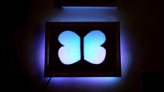
I started with the idea of making a magic mushroom mirror. Laid out on the floor it looked so lovely! But I quickly realized I made my mushrooms a bit too big and heavy to securely attach in this way.
I scrapped that idea and instead found a lovely oak log that was already covered in wood-ear mushrooms. I used hot glue to secure the mushrooms to the top of the log, clustering them in groups of 2 or 3, and winding any excess wire around the mushroom stems.
Once they were all attached, I glued some preserved moss onto the log in between the mushrooms to cover up the wires and add a little more whimsy. It led to such a delightful result!